AGRI-ROVER 3D CAD PRO

Autonomous Variable-Geometry Crop Sprayer & Inspection Rover

Clearance: 3.50 ft (1.07 m)
Total Width: 5.50 ft (1.68 m)
Steer: +0.0°
Spray: ACTIVE (4.2 Bar)

Component Name

Description of the component.

GUIDED CAD TOUR
Step 1 of 6

1. Central Chassis Frame

4.5 ft Base Frame with Quick-Swap Payload Tooling

The central chassis provides the primary load-bearing foundation spanning 4.5 ft...

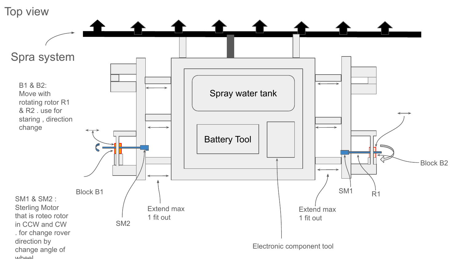
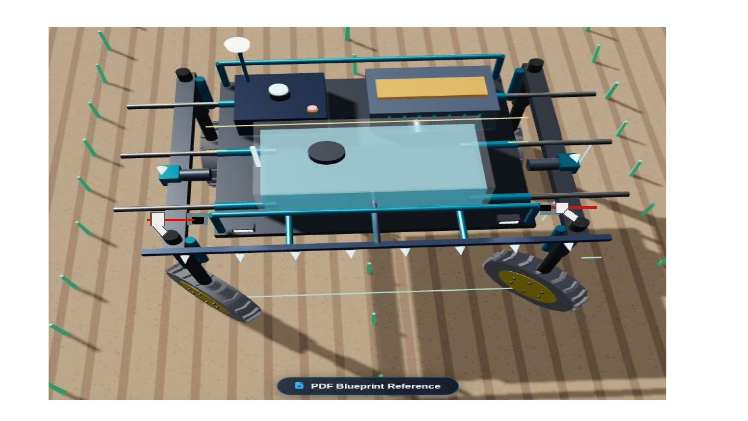
Top View Specifications: Main body (4.5 ft base width), Dual 1.0 ft lateral extension arms (left & right), SM1 & SM2 steering motors with rotating rotors R1 & R2, Spray water tank, Battery tool, Electronic component bay, and forward 8-nozzle spray system.

Spra System (8 Front Nozzles) Base Body: 4.5 ft (1.37 m) Spray Water Tank (150 L) Battery Tool LiFePO4 Pack Electronic Component Tool RTK GPS + LiDAR 1.0 ft Ext (SM2) 1.0 ft Ext (SM1) Full Span Width: 6.5 ft (1.98 m)
Rover Design Page 1 Blueprint Scan

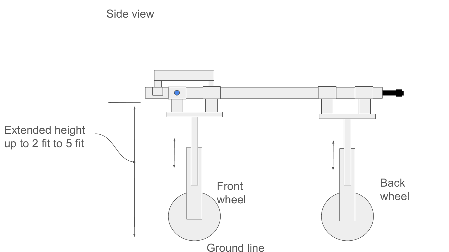
Side View Clearance Specifications: Vertical telescopic portal strut columns enable clearance height adjustment from 2.0 ft minimum (low seedlings) to 5.0 ft maximum (tall corn & mature crops).

Ground Level (Y = 0) Front Wheel Rear Wheel Main Chassis Body & Payloads Chassis Position at 2.0 ft Min Clearance 5.0 ft (Max) 2.0 ft (Min) Corn Canopy (Clearance Fit)
Rover Design Page 2 Blueprint Scan

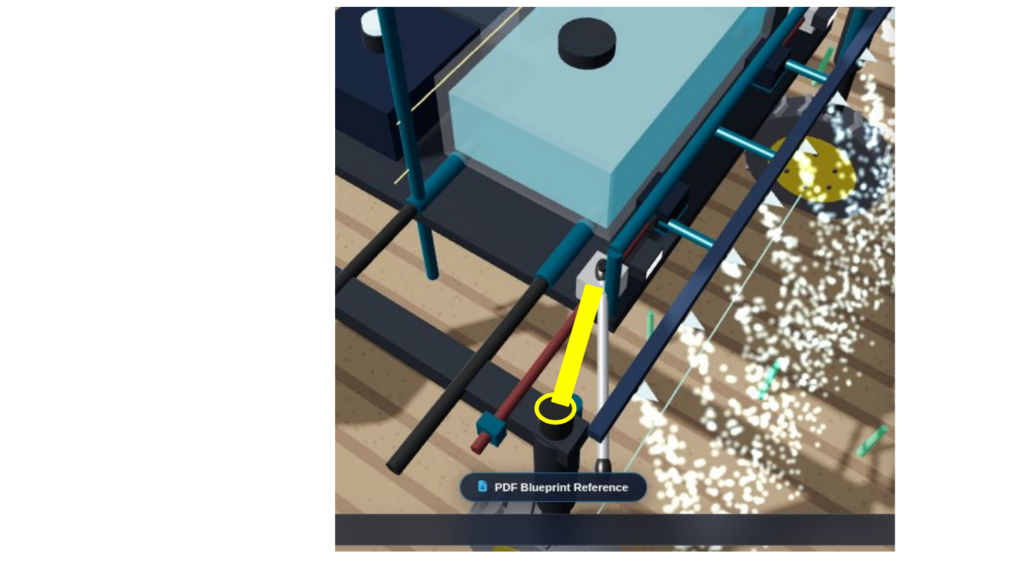
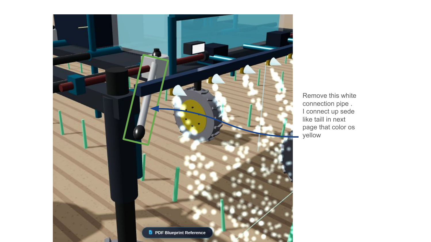
Top Yellow Connection Pipe Specifications: As detailed in Connection_Pipe.pdf, the connection pipe is top-mounted (yellow) on the upper plane and connects the moving carriage nut to the top pivot cap of the portal wheel strut column.

TOP-MOUNTED YELLOW CONNECTION PIPE (Connection_Pipe.pdf) Main Chassis Deck (4.5 ft Base Width) Motor ──► Rotor (Red) Moving block ──► Top Strut Pivot Cap ──► Yellow Connection Pipe (Top side level) WHEEL ◄── Motor Rotor (Red) ◄── Moving block ◄── Top Strut Pivot Cap Yellow Connection Pipe (Top side level) WHEEL Top-Mounted Configuration: Motor ➔ Red Rotor ➔ Moving Block ➔ Top Yellow Connection Pipe ➔ Strut Top Cap Upper plane linkage avoids crop entanglement and ensures direct steering torque delivery to wheel struts.
Connection Pipe Page 2 Blueprint Scan

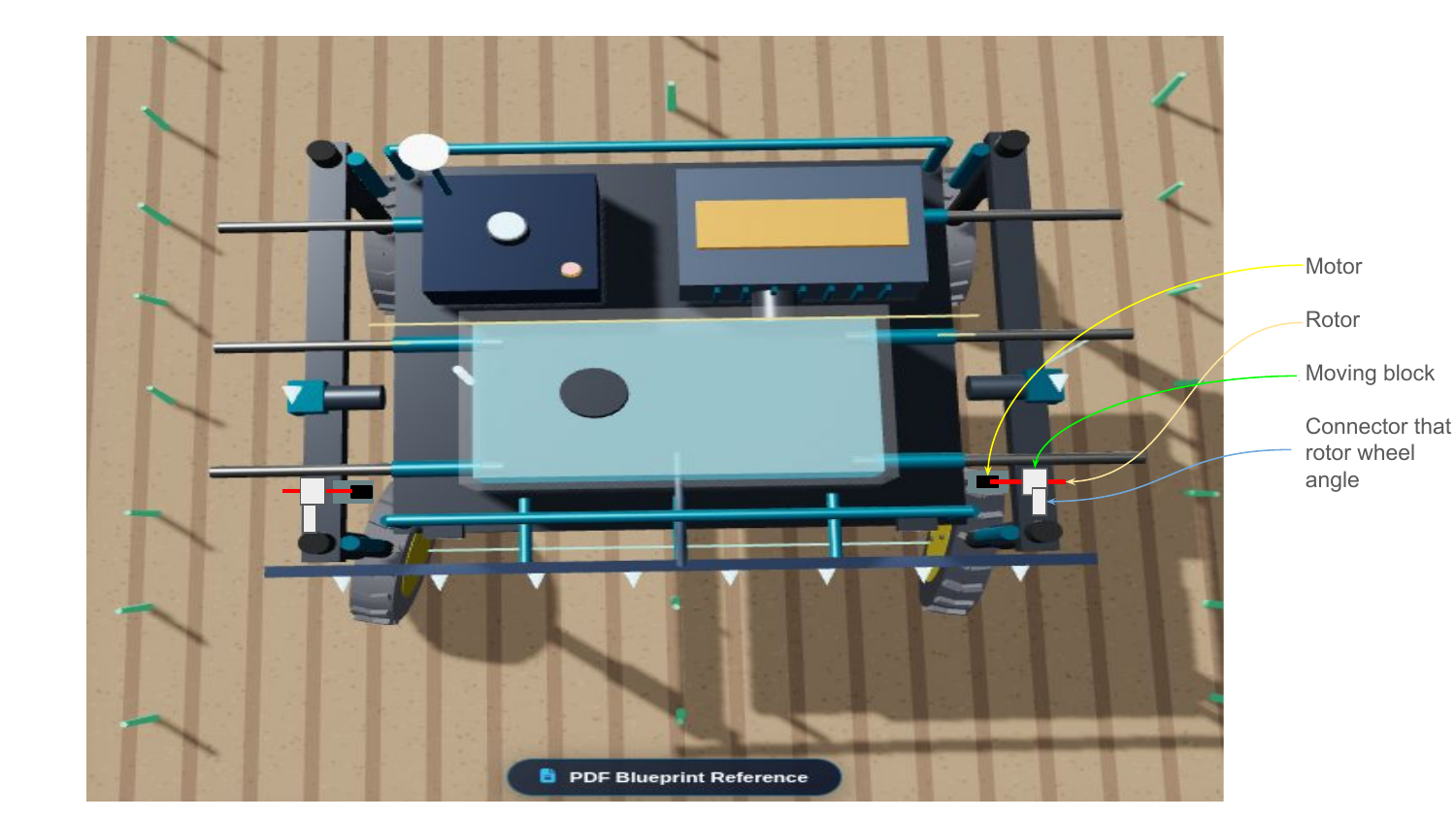
Steering Actuator Mechanism (new_string_idea.pdf): Motor drives threaded red rotor spindle rod, causing white carriage nut to translate linearly, pushing/pulling the tie rod to turn the wheel angle.

LEAD-SCREW STEERING ACTUATOR KINEMATICS (new_string_idea.pdf) Motor (Black Box) Rotor (Red Threaded Lead Screw) Moving block (Linear Carriage Nut) Connection Pipe Wheel Pivot Kinematic Formula: Linear Stroke Δx = Pitch × Revolutions Steering Angle θ = arcsin(Δx / Arm_Length) ➔ High precision holding torque with zero backlash.
new_string_idea.pdf Page 2 Blueprint Scan

Original High-Resolution PDF Blueprint Archive: Browse through all extracted blueprint pages from Rover_design.pdf, Connection_Pipe.pdf, and new_string_idea.pdf.